whatsapp: 0086-15153112822
Electronics Trainer

Didactic Equipment Electrotechnics Theory, Electric Traction Trainer Electrotechnics Theory Trainer Electrical Training Equipment 
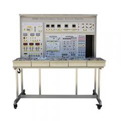
Item No.: ZE3302
ZE3302 The electric teaching aid adopts advanced design, and the experimental panel can be replaced freely. Students can replace it according to different training requirements.
INQUIRY
Description

ZE3302 Didactic Equipment Electrotechnics Theory, Electric Traction Trainer Electrical Training Equipment 
1 Product overview
1-1 Overview
1. The electric teaching aid adopts advanced design, and the experimental panel can be replaced freely. Students can replace it according to different training requirements.
2. The experimental instruments are digital display with high precision. The power and instruments used in this trainer are equipped with a reliable personal safety protection system.
1-2 Features
3. Applicable to the teaching of "Basic Theory of Electrical Engineering" and "Electrical Technology". Thanks to its good expansion capabilities, the trainer can be extended to other training content such as "Programmable Logic Controller Technology" and "Motor Variable Frequency Control".
4. The front panel of the hanging test board is drawn with schematic diagrams and symbols, and the other side is welded with related parts. Components that need to be measured or observed use a locking connector. The experimental circuit adopts the unit circuit mode design. Each unit circuit is based on the basic circuit. By connecting different components or combining different circuits, students can practice various training contents on the trainer.

2 Performance parameters
(1) Input power: three-phase five-wire system 380V±10% 60Hz
(2) Dimensions: 1600mm × 800mm × 1500mm
(3) Machine capacity: <2KVA
(4) Weight: <250kg
(5) Working conditions: ambient temperature -10 ° C ~ +40 ° C Relative humidity <85% (25 ° C)
4 Experiment list
Electrician basic electric drag part
Experiment 1 The use of basic electrical instruments and the calculation of measurement errors
Experiment 2 Method for reducing the measurement error of the meter
Experiment 3 Ohm's law
Experiment 4 Instrument Range Extension
Experiment 5 Mapping of volt-ampere characteristics of linear and nonlinear circuit components
Experiment 6 Determination of potential and voltage and drawing of circuit potential map
Experiment 7 Verification of Kirchhoff's Law
Experiment 8 Verification of the superposition principle
Experiment 9 Equivalent transformation of voltage source and current source
Experiment 10 Verification of Thevenin's Theorem

Test 11 Verification of Norton's Theorem--Determination of Equivalent Parameters of Active Two-End Network
Experiment 12 Determination of maximum power transmission conditions
Experiment 13 Two-port network test
Experiment 14 Reciprocity Theorem
Experiment 15 Experimental study of controlled sources VCVS, VCCS, CCVS, CCCS
Experiment 16 Observation and measurement of typical electrical signals
Experiment 17 Response test of RC first-order circuit
Experiment 18: Study on the response of second-order dynamic circuit
Experiment 19: Determination of impedance characteristics of R, L and C components
Experiment 20 RC string, parallel double T frequency selection network characteristics test
Experiment 21: Research on R, L, C Series Resonant Circuits
Experiment 22 RC dual T frequency selective network
Experiment Twenty-three Study of Phasor Trajectories in RL and RC Series Circuits
Experiment 24: R, L, C component characteristics and AC parameters determination
Experiment 25 Measurement of AC circuit parameters
Experiment 26 Study on phasor of sinusoidal steady-state AC circuit
Experiment 27 Test of characteristics of single-phase iron core transformer
Experiment 28: Determination of winding polarity of transformer
Experiment 29 Verification of single-phase watt-hour meter
Experiment 30 Measurement of power factor and phase sequence
Experiment 31: Negative Impedance Converter
Experiment thirty-two gyrator
Experiment 33: Fluorescent lamp, white woven lamp, watt-hour meter installation control circuit
Experiment 34: Use of three-phase squirrel cage asynchronous motor
Experiment 35: Three-phase asynchronous motor jog
Experiment 36: Three-phase asynchronous motor self-locking control circuit
Experiment 37: Three-phase asynchronous motor can both jog and self-lock control lines
Experiment 38: Contactor interlocking positive and negative control line
Experiment 39: Button interlocking positive and negative control line
Experiment 40 button and contactor double interlocking positive and negative control line
Analog circuit section
Experiment 1 Use of commonly used electronic instruments
Experiment 2 Transistor common emitter single tube amplifier
Experiment 3 FET amplifier
Experiment 4 Negative Feedback Amplifier
Experiment 5 emitter follower
Experiment 6 Difference Amplifier
Experiment 7 Integrated Operational Amplifier Indicator Test 146
Lab 8 Basic Applications of Integrated Operational Amplifiers (I)--- Analog Operational Circuits
Lab 9 Basic Application Gates for Integrated Operational Amplifiers (II) --- Active Filters
Lab 10 Basic Applications of Integrated Operational Amplifiers (III)--- Voltage Comparators
Lab 11 Basic Applications of Integrated Operational Amplifiers (IV) --- Waveform Generators
Experiment 12 RC sine wave oscillator
Experiment 13 LC sine wave oscillator
Experiment 14 Assembly and debugging of function signal generator
Experiment 15 Voltage Controlled Oscillator
Experiment 16 Low Frequency Power Amplifier (I) --- OTL Power Amplifier
Experiment 17 Low Frequency Power Amplifier (I) --- Integrated Power Amplifier
Experiment 18 DC regulated power supply (I) --- series transistor regulated power supply
Experiment 19 DC regulated power supply (II) --- integrated voltage regulator
Experiment 20 Thyristor controllable rectifier circuit
Experiment 21 Application Experiment --- Temperature Monitoring and Control Circuit
Experiment Twenty-two Comprehensive experiment Design and debug of a multimeter using operational amplifiers
Appendix I Principles and Use of Oscilloscopes
Appendix II Detection of common electronic components with a universal meter
Appendix III Resistor Nominal Value and Accuracy Color Circle Marking Method
Appendix IV Amplifier Interference, Noise Suppression, and Elimination of Self-Excited Oscillation
Digital circuit part
Experiment 1 Transistor Switching Characteristics, Limiter and Clamp
Experiment 2 Logic function and parameter test of TTL integrated logic gate
Experiment 3 Logic function and parameter test of CMOS integrated logic gate
Experiment 4 Connection and drive of integrated logic circuits
Experiment 5 Design and test of combinatorial logic circuit
Experiment 6 Decoder and its application
Experiment 7 Data Selector and Its Application
Experiment 8 Trigger and its application
Experiment 9 Counter and its application
Experiment 10 Shift register and its application
Experiment 11 Pulse Distributor and Its Application
Experiment 12 Using a Gate Circuit to Generate a Pulse Signal--Self-excited Multivibrator
Experiment 13 Monostable Trigger and Schmitt Trigger---Pulse Delay and Waveform Shaping Circuit
Experiment 14 555 time base circuit and its application
Experiment fifteen electronic stopwatch
Experiment 16 Electronic code lock
Experiment 17 Digital Frequency Meter
Experiment 18
Experiment 19 D/A, A/D converter