whatsapp: 0086-15153112822
Pneumatic Training Equipment

PLC Electro Pneumatic Trainer, Pneumatic Training Equipment For College

Item No.: ZMP1104
ZMP1104 PLC Electro Pneumatic Trainer Vocational Training Equipment Didactic Equipment for college, university
INQUIRY
Description
ZMP1104 PLC Electro Pneumatic Trainer Vocational Training Equipment Didactic Equipment
Brief introduction:

The experimental device uses double-sided structure, ie an experimental table provides places for doing pneumatic and hydraulic test experiment for two groups of four students. It can simultaneously do double-sided comprehensive pneumatic and hydraulic experiments, optimizing and sharing resources and improving products’ performance. Its overall structure is simple and practical.
The training equipment is iron double matte dense spray pattern, which is beautiful, durable and practical. The basic configuration is as following: 1 set of pneumatic training components; 1 set of pneumatic PLC control module; 1 piece of low noise air compressor; 1 set of hydraulic training components; 1 set of hydraulic PLC control module; 1 piece of hydraulic test pump. The optional configuration is the computer.

This training system uses a dedicated independent hydraulic test pump with variable speed DC motor system with oil pressure setting function. You can set safe working pressure of output oil pressure. With all common hydraulic components: Each hydraulic component is equipped with mounting plate, which can be easily and freely placed in the aluminum alloy hydraulic components on the panel (the panel with "T" slot in the form of aluminum alloy structure). Oil lap using quick-change connectors; convenient disconnect without leakage.
With this set of training equipment, you can do pneumatic control and hydraulic control circuit and its corresponding basic application experiments. It can also be integrated with each other to carry out the following experiment: realized pneumatic - electric control, pneumatic - hydraulic control, electric - fluid control, and pneumatic - electric - hydraulic integrated control.

Product Detail

Technical parameters of pneumatic part
 
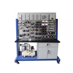
  1. Pneumatic components
2. Main technical parameters:
2.1 Power: AC 220V 50HZ
2.2  DC power: input AC220V, output DC 24V/2A
2.3  Air compressor
2.4  Motor power: 250W  power: AC220V
2.5  Nominal capacity: 10L
2.6  Rated output voltage: 1Mpa
2.7  Training Equipment dimensions: 1500mm*900mm*1700mm
3.   Basic experimental Pneumatic circuit
3. single-acting cylinder commutation circuit
4. double-acting cylinder commutation circuit
5. single-acting cylinder speed control loop
6. double-acting cylinder-way flow control loop
7. double-acting cylinder bi-speed circuit
8. the speed loop for access
9. buffer circuit
10. the secondary pressure control loop
11. high and low voltage conversion circuit
12. counting loop
13. the delay loop
14. overload protection circuit

15. interlock circuit 1
16. single-cylinder reciprocating control loop
17. single-cylinder reciprocating continuous loop
18. linear cylinders, rotary cylinders loop sequence of actions
19. multi-cylinder sequence of actions loop
20. twin synchronized action loop
21. four-cylinder linkage loop
22. the unloading circuit
23. gate circuit type shuttle valve applications
24. quick exhaust valve application circuit
 
Configuration list of pneumatic part:
No   Item QTY
1 Air source Air compressor  XY5.2 dual connector 1 piece
2 Experimental table Experimental table 1 piece
3 Experimental bench Components fixed stand 1 piece
4  
Electrical control part
DC switching power supply unit(DC24V)    
1 set
Signal input unit
Relay control unit
5 Components Single-acting cylinder  QGX25×100 1 piece
6 Components Dual-acting cylinder    GGX25×100 2 pieces
7 Components Triple pieces          AC2000 Triple pieces 1 piece
8 Components Pressure reducing valve
(with pressure gauge) AR2000
1 piece
9 Components Manual valve          4H210-08 1 piece
10 Components Single solenoid valve(two five-way)
4V210-08(DC24V)
2 pieces
11 Components Dual solenoid valve(two five-way)
4V210-08(DC24V)
1 piece
12 Components Single solenoid valve(three five-way)
4V210-08(DC24V)
1 piece
13 Components Single gas valve
(two- pass) 4A210-08
2 pieces
14 Components Dual gas valve (two-pass) 4A210-08 2 pieces
15 Components Rotary valve(machine  control) MOV-2 1 piece
16 Components Rotary valve(button) MOV-3A 1 piece
17 Components Door type shuttle valve ST-02 2 pieces
18 Components Quick exhaust valve 1/4 QE-02 2 pieces
19 Components One-way throttle valve RE-02 2 pieces
20 Components One-way throttle valve JSC601 7 pieces
21 Components Way valve 1/4 2 pieces
22 Components Sequence valve 2 pieces
23 Components Gas volume 1 piece
24 Components Six-way 2 pieces
25 Components Limit switch 4 pieces
26 Material Experimental manual 1 piece
27 Components   2 pieces
28 Components screwdriver 2 pieces
29 Components  150*19 1 piece
30 Components Pliers 1 piece
31 Components Scissors 1 piece
32 Components Muffler(small) 1/8 2 pieces
33 Components Muffler(big) 3/8 1 piece
34 Components Tee (T-Tee) Φ6 4 pieces
35 Components Tee(Y-type reducing tee) Φ8-Φ6 1 piece
36 Components Four way Φ6 2 pieces
37 Components L-type (threaded two-pass) 601 2 pieces
38 Components L-type (threaded two-pass) 602 2 pieces
39 Components Vent plugs Φ6 25 pieces
40 Components Fuse 2.5A 5 pieces
41 Components Button switch 3 pieces
42 Components Windpipe PU Windpipe 6*4 1 roll
Technical Parameter of the hydraulic part
1. Main technical parameters:
 Power: AC220V 50HZ
 DC power input AC220V, output DC24V/3A
 Motor power of the hydraulic pump: 400W, adjustable speed range: 0-1500RMP
Size: 550mm*350mm*450mm
 the hydraulic pump works with a distance of 1.5m from the hydraulic table, the distant noise is 58Db
 The dimensions of the training device: 1500*900mm*1700mm
2. Experiment topics:
1. commutation loop with a manual valve
2. latching loop with “o” “M” type function valve
3. latching loop with pilot operated check valve
4. pressure settings loop
5. two grades pressure loop
6. decompression loop with reducing valve
7. pressurized loop with pressurized cylinder
8. unloading loop with H type valve
9. inlet throttle loop
10. back to the oil throttle loop
11. speed control gear pump speed loop
12. composite speed loop of speed gear pump and speed valve