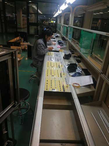
TB230621S49 Basic Electronic-Electric Training System Didactic Equipment Electronics Laboratory Equipment
1. Main composition and technical parameters
1. DC regulated power supply: two channels of ±5V/1A, two circuits of 0~18V/0.75A continuously adjustable (through proper connection, 0~±18V and 0~36V continuously adjustable power supply can be obtained), +5V power supply It also has short-circuit alarm and indication functions, and each power supply has a short-circuit cut-off automatic recovery protection function.
2. DC signal source: -5V ~ +5V continuously adjustable two ways.
3. AC power supply: 0V, 6V, 10V, 14V tap power supply one way, center tap 17V power supply two ways, each power supply has short-circuit protection and automatic recovery function, and there are several 220V single-phase three-core sockets on the left and right sides of the control panel.
4. Function signal generator: the output frequency range is 2Hz~2MHz, and the peak-to-peak output amplitude is 0~16VP-P. It can output three waveforms: sine wave, square wave, and triangle wave, which can be selected by the keyboard switch. The output frequency is divided into seven frequency bands. There are also three LED digital tubes to display the output amplitude (peak-peak value). The output attenuation is divided into four levels of 0dB, 20dB, 40dB, and 60dB, which are selected by two "attenuation" buttons.
5. Six-digit display frequency meter: The measurement range of the frequency meter is 1Hz to 10MHz, and there are six common-cathode LED digital tubes for display.
6. DC digital voltmeter: divided into 200mV, 2V, 20V, 200V four gears, direct key switch switching, three and a half digit display, input impedance 10MΩ, precision 0.5.
7. DC digital mA meter: divided into 2mA, 20mA, 200mA three gears, direct key switch, three and a half digit display, precision 0.5 grade.
8. Equipped with 1mA/100Ω mirror pointer type precision DC mA meter, relay, speaker, buzzer, oscillating coil, thyristor, 12V signal lamp, power resistor, bridge stack, diode, integrated voltage regulator block, capacitor, triode , buttons and potentiometers, etc.
9. The analog electric experiment function board is equipped with four sockets for loading and unloading fixed line experiment small boards, and is equipped with a common emitter single-tube amplifier/negative feedback amplifier experiment board, an emitter follower experiment board, and an RC sine wave oscillator There are five experimental boards, differential amplifier experimental boards and OTL power amplifier experimental boards.
10. The experimental connection points and test points adopt high-reliability self-locking anti-rotation stacking sockets and test loopers, and are equipped with high-reliability round-foot integrated block sockets (40P 1 piece, 14P 1 piece, 8P 2 pieces) and silver-plated long purple Copper tubes, etc., for inserting various integrated blocks, triodes, capacitors and resistors.
11. The experimental function board is made of 2mm thick copper-clad board. The graphic symbols, characters and connections of components are printed on the front, and the corresponding connections and corresponding devices are soldered on the back.
2. Training projects
1. Single-stage, 2-stage and differential amplifier experiments
2. Emitter follower experiment
3. Proportional and operational circuit experiments
4. Integral and differential circuit experiments
5. Waveform generating circuit experiment
6. Voltage comparator experiment
7. Linear regulator circuit experiment
8. Adjustable voltage regulator circuit experiment
9. Waveform conversion circuit experiment
